Home My New Layout Diagram of My  Layout My OLD Layout LV & WR MRRC Scenery Work C&O Berkshire &
Live Trains
CTC How-To Lesson

CTC Wiring

(Centralized Traffic Control)


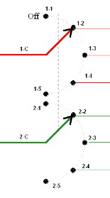
The schematic (drawing 14) for a rotary switch looks much like is physical layout. The common terminal may be marked A, A-C (for circuit A common), 1-C (for circuit #1 common), or some similar manner. The individual position contacts will be marked A-1 (for circuit A - position 1), 1-1 (for circuit 1 - position 1), or similar. The most common method is 1-C (for circuit #1 common), 1-1 (for circuit 1 - position 1), 1-2 (for circuit 1 - position 2), 1-3 (for circuit 1 - position 3) …... Diagram 14 shows this method. 1-C is the pole (common contact) and the others are the switched contacts 1-5.
The dashed curved line through the contacts indicates the 'swing' of the pole.

Diagram 14

Diagram 15
Multiple pole switches will be drawn to look like stacked wafers regardless of the actual physical construction. Diagram 15 is for a two pole five position rotary switch. The red circuit is circuit 1 while the green is circuit 2. This is similar to the switch I used. By leaving the first position contacts empty (you can even snip the contacts off to prevent confusion later) it serves as an Off-1-2-3-4 rotary switch. Through this article, I will continue to refer to the terminals on this switch as shown (1-C, 1-1, …. 2-C, …..). It is critical that your CAB control switches can handle the current pull expected so use at least 2 amp (2A) switches. I suggest about 4A - 5A switches for long, dependable life.
The dashed straight line through both poles indicates both section work ( turn) together as a single unit.
Wiring the CAB control rotary switches is similar to wiring the direction control toggle switches. First, determine how the terminals are located on the switches you have. Look for tiny stamped indicators. It should have an A circuit and a B circuit but may be labeled other ways. Most better quality switches come with an information sheet. Diaram 16 shows the bottom of a typical 2 Pole - 5 Position rotary switch. The dashed red line shows the separation of the two poles (1 & 2). Notice that the common terminals are located on an inner circle. This is a switch with two poles (circuits) on a single wafer (as in the last example on the previous page).
Diagram 16

Diagram 17
The idea here is to select which CAB (power pack) is to be routed to the track section. The wires will actually connect to the direction control toggle switch (covered in previous sections) and then on to the track in order to allow you to determine the direction of travel for the track section this switch controls. The various CAB wires will connect to the switch positions (1-6) so the selected CAB power can be switched to the common terminals. The common terminals go toward the track section. Use contact 1 for the OFF position, contact 2 for CAB#1, contact 3 for CAB#2, contact 4 for CAB#3, and contact 5 for CAB#4. Be careful to not let this confuse you. Again, if you snip off contacts 1-1 and 2-1, you can't connect to the OFF position terminals.

Now you know all the pieces required to wire up your layout for realistic operations.
Click here to go to the next page for step-by-step wiring directions on cab switching.