Home My New Layout Diagram of My  Layout My OLD Layout LV & WR MRRC Scenery Work C&O Berkshire &
Live Trains
CTC How-To Lesson

CTC Wiring

(Centralized Traffic Control)

Diagram 5

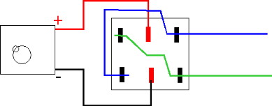
Your cab ^ control ----------bottom view ^ of the DPDT ---------------to the rails ^
switch and the terminals.

When the lever is flipped to the right, + (from your controller) is connected to the top-left contact (green wire) while - is connected to the bottom-left contact (blue wire).
When the lever is flipped to the left, + is connected to the bottom-left contact (blue wire) while - is connected to the top-left contact (green wire).

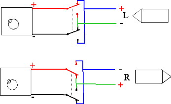
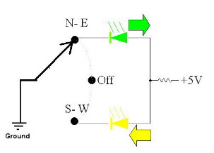
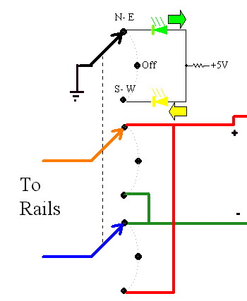
CTC Wiring basics.
Now, imagine a section of track running left-to-right in front of you (see below). For an engine to run to the right, + must be on the bottom rail. For an engine to run to the left, + must be on the top rail.
Now, all we have to do is control how we keep + on the right and - on the left with a DPDT switch. If you wire your cab control as shown to the left, it is simply a matter of connecting the blue and green wires to the rails so the engnes run in the direction (N-S or E-W) you flip the lever (see circuit to left) (you may have to reverse the wires).
Here are the schematics (right) explaining the process.
In the top circuit, the toggle is flipped up (= left) and places + on the top rail and - on the lower one. With the engine going left, the + is on the right-side rail.
In the bottom circuit, the toggle is flipped down (= right) and places + on the bottom rail and - on the top one. With the engine going right, the + is again on the right-side rail.
Once you have wired each section this way, all you have to do is flip the toggle for each section BEFORE your engine enters that section. This wiring will reverse (switch) the + and - connections on the blue section (in the descrition above with the 4 diagrams) to finish the loop and the direction change if you flip the toggle switch for the blue section while the engine is crossing the black or green sections (before it gets back to the blue section).
Entering the loop.

Exiting the loop - reversed now.
Diagram 6


Another great help when running your trains is to have lights on your CTC panel to show the direction of travel on each section of track. I did not use these on the old layout but certainly will on the new one (It often 'misread' how the switches were set). For indicators, you need a harder to find switch: a 3PDT On-Off-On switch. The third pole contacts are used to simply turn on an indicator (light) for each direction. This can be low-voltage LEDs or regular bulbs but I recommend LEDs. If you have a 5VDC power supply on your layout, it can be the power source for the LEDs. Each led will need a resistor and you should use two colors for your LEDs (for directions). I assigned the YELLOW LEDs for South and West and GREEN for North and East.

The LEDs are polarized (+/- voltage must be right) and must be inserted with the connections in the correct direction. Look at the LED from the top and observe each has a 'flat side' on its base. That side always connects to the - (negative) or ground side. Connect the leads on the round side of one GREEN LED and one YELLOW LED to a 330 ohm 1/8W resistor. Connect the remaining side of the resistor to the + 5VDC source. Connect the lead on the flat side of each LED to the appropriate third pole contact on the switch (to turn the light on when the switch is flipped). Connect the center contact of the third pole to ground (-).
Diagram 7

Diagram 8
Here's the actual schematic of the complete
circuit with indicators.

OK. Now you're ready to build your own CTC panel with direction control (& reversing) switching and direction indicators.

Of course, you can't stop here. Every serious (and even somewhat serious) model railroader wants the ability to run several trains from several CABs (power packs). That will require switches on the CTC to allow you to select which cab controlls power to each section of track. The other, and more complicated part of the CTC panel is managing which contoller powers each section of track. Click here to go to the next page and learn about cab switching.